The analysis applied by ICE is based upon the widely published theory of an expansion and reflection pulse occurring within the exhaust pipe. The premise being that the pressure pulse travels at the speed of sound, and that the pipe length is arranged to return the pulse between transfer and exhaust port closure. When suitably timed a higher cylinder MEP should occur. It is important to appreciate that the so-called Tuned Length refers to the RPM at which maximum IMEP is predicted, this is not necessarily the RPM at which maximum BHP occurs. Fitting a suitable exhaust pipe should provide a useful increase in torque. A problem arising from this is that at RPM above and below the tuned RPM, scavenge and exhaust flow can be disrupted. Hence the RPM range over which satisfactory conditions occur is limited by the expansion and compression ratios of the pipe and system.
In most circumstances the exhaust timing and pipe length are fixed. However some engines incorporate variable timing to widen the operational range. The reason for this is that at moderate RPM very long pipes would be required. Hence the exhaust period is reduced, at low RPM. The reduction in time between open and plose giving a pulse length nearer to the tuned length provides a wider satisfactory RPM range
Actual pulse speed is not constant over the RPM range because the exhaust temperature varies. The predicted pulse speed is likely to be within the range 1400 - 1800 ft per second. It will be appreciated that mixture strength becomes hyper critical when a tuned pipe is fitted because the pulse speed is temperature and not pressure sensitive.
The rate of change of expansion and compression ratios per degree of engine crankshaft rotation is not linear. Hence the pressure and temperature at the exhaust port does not change in direct proportion to lapsed time. A consequence of this is that the shape of the flow curves can be substantially different over the engines RPM range. A parallel exhaust pipe can enhance flow, it provides a linear expansion and compression ratio proportional to the pulse speed. If the pipe diameters vary throughout the tuned length, the rate of change of ratio is no longer linear. A consequence of this is that by suitable modification of shape a pipe can be designed to suit and enhance the engine's flow characteristics. ICE includes options for alternative pipe designs; these automatically determine the pipe ratio's based upon the data input.
Whilst not considered as part of the tuned length, the exhaust stinger or tailpipe performs an important functions apart from noise reduction. It acts as the pipe clearance volume, increasing the volume softens the rulse ratios, reducing the diameter increases the reflection pulse pressure.
Due to the fact that the exhaust pipe exit is always open to atmospheric pressure the program applies incremental expansion and compression ratio's based upon pulse speed; and distance travelled within the pipe tuned length. Flow into and out of the pipe being calculated simultaneously as this can occur throughout the full 360 degrees of rotation. The fresh pulse, starting at each exhaust port opening; may be affected by the pulse from the previous cycle. The pressure and temperature at the exhaust port is determined by these calculations.
Whilst the pipe shape is fixed by design, the rate of change of ratio at different RPM changes portion to elapsed time. Hence expansion and compression can take place out of phase with cylinder displacement. Large changes in pipe diameter can create excessive eatios resulting in limited useful RPM range.
ICE includes a pipe design prediction facility. This is based upon empirical data extracted from Gordon Blair's book Design and Simulation of Two Stroke Engines. Ice does not apply this data to determine performance. It has been included for comparison purposes to the design evaluation predictions generated by the program equations (a wider range of pipe designs can be evaluated by ICE).
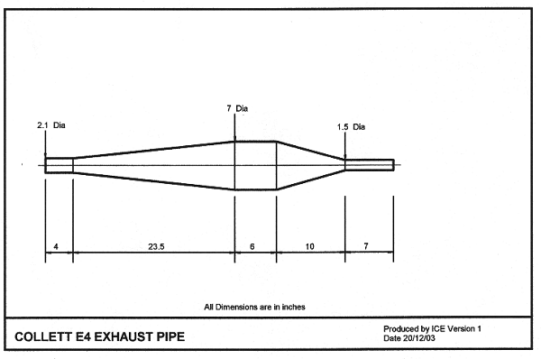
The pipe illustrated here is intended to be applied to an experimental Two Stroke motorcycle, because the engine is fitted with a sleeve valve mechanism asymmetric timing of Exhaust and Scavenge is feasible. The objective being to establish if improved fuel consumption is feasible, the predictions shown here are for symmetric timing. The following PV diagram has a significantly different shape when compared to an engine not fitted with a pipe. This has been plotted at maximum IMEP. Exhaust extensions can increase power output even if no silencer is fitted. It appears that an improved discharge coefficient occurs. The flow column assists extraction and scavenge process, hence Exhaust port shape as the gas exits the cylinder is significant in that there should not be undue turbulence, or break up of flow. A rapid drop in cylinder pressure prior to opening the scavenge ports may not be beneficial if the exhaust gas column cannot be sustained, hence the timing of exhaust and scavenge porting must be reviewed in conjunction with the proposed exhaust system.
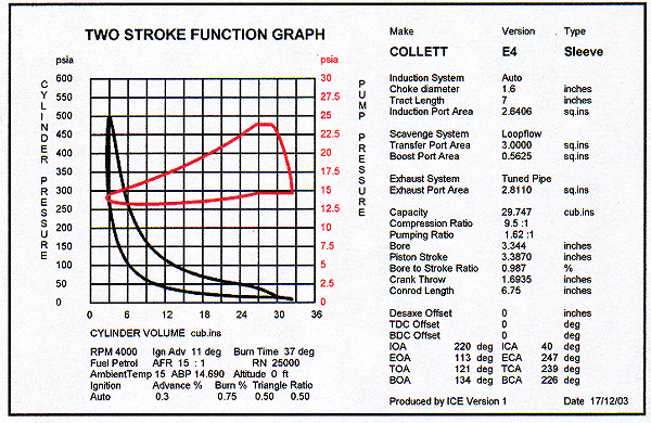
The power output prediction curve for the COLLET E4 500 cc Loopflow Sleeve Valve engine when fitted with a high torque pipe clearly illustrates a dramatic increase in BHP at 5000 RPM and a critical condition between 2000 to 3000 RPM. As the engine is fitted with an automatic induction system the valve can respond to the exhaust pulse. However, this is difficult to predict because of system loss and pulse speed
The following performance table displays related data. It is important to record all engine data when evaluating an exhaust system as it may be desirable to modify the ports and timing. The data here is different to the default file which indicates a better BHP for an engine not fitted with a pipe.
| ICE - TWO STROKE ENGINE PERFORMANCE TABLE | Produced by ICE Version1.7.0 Date 01/06/2008 | |||||||||||
| Make COLLETT Version E4 Type Sleeve Scavenge Loopflow Induction Auto Drive Effic 1 Sleeve Drive Ball | ||||||||||||
| Bore 3.344 | PStroke | 3.387 | Capacity | 29.747 | CR 9.5 : 1 | Choke 1.600 | Tract Length 7.000 | |||||
| CVol 2.5709 | CStroke | 2.488 | EStroke | 2.488 | ||||||||
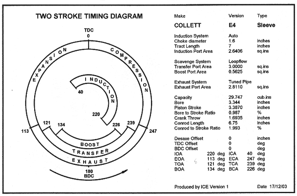
| TIMING | TDC | BDC | IOA | ICA | EOA | ECA | TOA | TCA | BOA | BCA | S.Phase | |
| degree | 360 | 180 | 220 | 80 | 111 | 249 | 125 | 235 | 132 | 228 | 180 | |
| TEST CONDITIONS | ||||||||||||
| Ambient Temp | ABP | Altitude | Fuel | AFR | Density | RN | Ignition | Adv % | Burn % | Triangle | Ratio | Exhaust |
| 15 degrees C | 14.69 | 0 ft | Petrol | 15 | 0.0764 | 25000 | Auto | 0.3 | 0.75 | 0.5 | 0.5 | No Pipe |
| RPM | 2000 | 2500 | 3000 | 3500 | 4000 | 4500 | 5000 | 5500 | 6000 | 6500 | 7000 | 7500 |
| Advance deg | 5 | 7 | 8 | 10 | 11 | 13 | 14 | 15 | 17 | 18 | 20 | 21 |
| Combustion | 18 | 23 | 28 | 32 | 37 | 42 | 46 | 51 | 56 | 61 | 65 | 70 |
| IMEP psi | 84.49 | 86.09 | 87.66 | 87.96 | 88.24 | 87.87 | 86.94 | 85.69 | 84.34 | 81.22 | 77.54 | 73.45 |
| IHP | 12.693 | 16.167 | 19.754 | 23.125 | 26.513 | 29.704 | 32.655 | 35.402 | 38.012 | 39.655 | 40.773 | 41.378 |
| PMEP psi | 4.71 | 4.95 | 5.17 | 5.34 | 5.44 | 5.49 | 5.49 | 5.45 | 5.37 | 5.25 | 5.09 | 4.92 |
| PHP | 0.708 | 0.929 | 1.165 | 1.404 | 1.636 | 1.856 | 2.062 | 2.252 | 2.422 | 2.562 | 2.677 | 2.771 |
| FHP | 0.804 | 1.094 | 1.562 | 2.227 | 3.108 | 4.261 | 5.717 | 7.516 | 9.732 | 12.419 | 15.675 | 19.455 |
| BHP | 11.182 | 14.143 | 17.027 | 19.495 | 21.769 | 23.587 | 24.876 | 25.634 | 25.857 | 24.675 | 22.421 | 19.153 |
| Torque Ft.lb | 29.364 | 29.713 | 29.81 | 29.254 | 28.583 | 27.529 | 26.13 | 24.479 | 22.634 | 19.937 | 16.823 | 13.412 |
| PFHP | 0.136 | 0.179 | 0.272 | 0.421 | 0.636 | 0.928 | 1.309 | 1.787 | 2.38 | 3.098 | 3.957 | 4.954 |
| RFHP | 0.188 | 0.24 | 0.293 | 0.343 | 0.393 | 0.44 | 0.484 | 0.525 | 0.564 | 0.588 | 0.605 | 0.613 |
| CJHP | 0.154 | 0.209 | 0.3 | 0.431 | 0.604 | 0.833 | 1.125 | 1.489 | 1.942 | 2.502 | 3.195 | 4.005 |
| CPHP | 0.168 | 0.207 | 0.268 | 0.36 | 0.478 | 0.638 | 0.845 | 1.105 | 1.44 | 1.869 | 2.421 | 3.07 |
| GPHP | 0.062 | 0.076 | 0.098 | 0.132 | 0.175 | 0.234 | 0.31 | 0.405 | 0.528 | 0.685 | 0.888 | 1.126 |
| DHP | 0 | 0 | 0 | 0 | 0 | 0 | 0 | 0 | 0 | 0 | 0 | 0 |
| SDHP | 0.095 | 0.183 | 0.33 | 0.54 | 0.822 | 1.187 | 1.644 | 2.205 | 2.879 | 3.677 | 4.609 | 5.685 |
| MEF % | 0.88 | 0.87 | 0.86 | 0.84 | 0.82 | 0.79 | 0.76 | 0.72 | 0.68 | 0.62 | 0.55 | 0.46 |
| BTE % | 0.17 | 0.17 | 0.17 | 0.17 | 0.17 | 0.16 | 0.16 | 0.15 | 0.15 | 0.13 | 0.12 | 0.1 |
| BSC Ratio | 0.805 | 0.793 | 0.787 | 0.794 | 0.801 | 0.816 | 0.841 | 0.877 | 0.921 | 1.003 | 1.133 | 1.351 |
| SE % | 0.5 | 0.5 | 0.5 | 0.5 | 0.49 | 0.48 | 0.47 | 0.46 | 0.44 | 0.42 | 0.4 | 0.38 |
| Crankshaft U | 0.007 | 0.007 | 0.007 | 0.007 | 0.007 | 0.007 | 0.007 | 0.007 | 0.007 | 0.007 | 0.007 | 0.007 |
| Crankpin U | 0.0075 | 0.0075 | 0.0075 | 0.0075 | 0.0075 | 0.0075 | 0.0075 | 0.0075 | 0.0075 | 0.0075 | 0.0075 | 0.0075 |
| Gudgeon U | 0.018 | 0.018 | 0.018 | 0.018 | 0.018 | 0.018 | 0.018 | 0.018 | 0.018 | 0.018 | 0.018 | 0.018 |
| Piston Thrust U | 0.04 | 0.04 | 0.04 | 0.04 | 0.04 | 0.04 | 0.04 | 0.04 | 0.04 | 0.04 | 0.04 | 0.04 |
| Piston Fit U | 0.02 | 0.02 | 0.02 | 0.02 | 0.02 | 0.02 | 0.02 | 0.02 | 0.02 | 0.02 | 0.02 | 0.02 |
| Piston Ring U | 0.1 | 0.1 | 0.1 | 0.1 | 0.1 | 0.1 | 0.1 | 0.1 | 0.1 | 0.1 | 0.1 | 0.1 |
| Disk U | 0 | 0 | 0 | 0 | 0 | 0 | 0 | 0 | 0 | 0 | 0 | 0 |
| Drum U | 0 | 0 | 0 | 0 | 0 | 0 | 0 | 0 | 0 | 0 | 0 | 0 |
| Sleeve Drive U | 0.007 | 0.007 | 0.007 | 0.007 | 0.007 | 0.007 | 0.007 | 0.007 | 0.007 | 0.007 | 0.007 | 0.007 |
| EOAT C deg | 1663.3 | 1574.7 | 1572.6 | 1575.2 | 1594.2 | 1602.8 | 1610.4 | 1623.3 | 1622.1 | 1620.4 | 1593.5 | 1578 |
| TOAT C deg | 1463.7 | 1418.8 | 1436.7 | 1453.2 | 1481.2 | 1497.6 | 1511.6 | 1529.2 | 1533 | 1535.6 | 1513.9 | 1502.3 |
| ECAT C deg | 404.4 | 417.1 | 421.4 | 425.6 | 429.2 | 432.4 | 435.5 | 438.8 | 440.9 | 445.1 | 450.1 | 455.4 |
| TCAT C deg | 403.6 | 416.8 | 421.4 | 425.7 | 429.4 | 432.6 | 435.8 | 439.2 | 441.3 | 445.6 | 450.6 | 455.9 |
| MET C deg | 607.3 | 620.6 | 639.1 | 657.8 | 678.3 | 697.2 | 715.2 | 734.9 | 750.7 | 766.4 | 774.2 | 784.1 |
| EPT C deg | 288 | 288 | 288 | 288 | 288 | 288 | 288 | 288 | 288 | 288 | 288 | 288 |
| EPulse Speed | 1591.5 | 1608.8 | 1632.6 | 1656.3 | 1682 | 1705.2 | 1727.1 | 1750.7 | 1769.4 | 1787.8 | 1796.9 | 1808.4 |
| EPulse Period | 138 | 138 | 138 | 138 | 138 | 138 | 138 | 138 | 138 | 138 | 138 | 138 |
| EPulse Time | 0.0115 | 0.0092 | 0.0077 | 0.0066 | 0.0058 | 0.0051 | 0.0046 | 0.0042 | 0.0038 | 0.0035 | 0.0033 | 0.0031 |
| ETuned Length | 109.81 | 88.81 | 75.1 | 65.3 | 58.03 | 52.29 | 47.67 | 43.93 | 40.7 | 37.96 | 35.42 | 33.27 |
| Induction lb | 2.2496 | 2.8038 | 3.3481 | 3.8685 | 4.3584 | 4.8125 | 5.2313 | 5.6174 | 5.9544 | 6.1867 | 6.352 | 6.4693 |
| Exhaust lb | 2.5382 | 2.8888 | 3.3532 | 3.7956 | 4.2247 | 4.6338 | 5.0172 | 5.366 | 5.7481 | 5.9908 | 6.1698 | 6.3239 |
| Transfer lb | 1.8882 | 2.3571 | 2.8186 | 3.2608 | 3.678 | 4.0654 | 4.4237 | 4.7551 | 5.047 | 5.2548 | 5.3997 | 5.5049 |
| Boost b | 0.354 | 0.4419 | 0.5285 | 0.6114 | 0.6896 | 0.7623 | 0.8294 | 0.8916 | 0.9463 | 0.9853 | 1.0124 | 1.0322 |
| Scavenge lb | 2.2422 | 2.799 | 3.3471 | 3.8723 | 4.3676 | 4.8277 | 5.2532 | 5.6467 | 5.9933 | 6.2401 | 6.4121 | 6.5371 |
| ExhaustPipe lb | 0 | 0 | 0 | 0 | 0 | 0 | 0 | 0 | 0 | 0 | 0 | 0 |
| I.Pulse Time | 0.0183 | 0.0147 | 0.0122 | 0.0105 | 0.0092 | 0.0081 | 0.0073 | 0.0067 | 0.0061 | 0.0056 | 0.0052 | 0.0049 |
| I.Pulse Period | 220 | 220 | 220 | 220 | 220 | 220 | 220 | 220 | 220 | 220 | 220 | 220 |
| I.Pulse Length | 242.2 | 193.76 | 161.47 | 138.4 | 121.1 | 107.65 | 96.88 | 88.07 | 80.73 | 74.52 | 69.2 | 64.59 |
| I.Tuned Length | 120.55 | 96.44 | 80.37 | 68.89 | 60.28 | 53.58 | 48.22 | 43.84 | 40.18 | 37.09 | 34.44 | 32.15 |
| ENGINE RECORD DATA Record 1 | ICE Version 1.7.0 | Date 01/06/2008 | |||||||
| Make COLLETT Version E4 | |||||||||
| Type Sleeve | |||||||||
| Loopflow Scavenge | |||||||||
| Auto Induction | |||||||||
| MaxCylRatio......... | 9.5 | MaxCaseRatio...... | 1.62 | Cylinder Offset...... | 0 | ||||
| Piston Diameter.... | 3.344 | Ring Width............ | 0.062 | Ring Number......... | 1 | ||||
| Piston Top............ | 1.9 | Length.................. | 4.9 | Weight.................. | 0.75 | ||||
| Gudgeon Pin Dia. | 0.687 | Type.................... | PB | Weight.................. | 0.25 | ||||
| Conrod Length..... | 6.75 | Weight.................. | 2 | ||||||
| Crank. Stroke....... | 3.387 | Shaft Diameter..... | 1.2 | Crankpin Diameter | 1.5 | ||||
| C.Shaft Bearing... | BB | C.Pin Bearing....... | RB | ||||||
| Crk.Balance %..... | 0.6 | Balance Rad........ | 1.69 | Drive Efficiency... | 1 | ||||
| Sleeve Drive...... | Ball | Link Length........ | 0 | Link Weight......... | 0 | ||||
| Sleeve Stroke...... | 1 | Sleeve Phase..... | 180 | Sleeve Weight.... | 2.5 | ||||
| S.DrivePin Dia...... | 0.75 | Pin Bearing............ | RB | ||||||
| S.Drive/Link Dia..... | 4 | Drive/Link Bearing. | BB | ||||||
| Sleeve Outer Dia. | 3.544 | Ball Centre Rad..... | 2.5 | ||||||
| Exhaust Number... | 3 | Width................... | 0.937 | Height.................. | 1 | ||||
| Exhaust to TDC..... | 3.2 | Overlap............... | 0 | Orifice Coefficient | 0.6 | ||||
| Transfer Number.. | 4 | Width................... | 1 | Height.................. | 0.75 | ||||
| Transfer to TDC.... | 3.6 | Overlap............... | 0 | Orifice Coefficient | 0.6 | ||||
| Boost Number....... | 1 | Width.................. | 1.125 | Height.................. | 0.5 | ||||
| Boost to TDC....... | 3.8 | Overlap............... | 0 | Orifice Coefficient | 0.6 | ||||
| Induction Number. | 0 | Width.................. | 220 | Height/Length...... | 0 | ||||
| Induction to TDC... | 0 | Induction Lead..... | 140 | Orifice Coefficient | 0.6 | ||||
| Ind.Drum Dia........ | 0 | Drum Bearing....... | NA | ||||||
| Ind.Disc IPR......... | 0 | Ind.Disc OPR....... | 0 | ||||||
| Venturi Lead........ | 0 | Width................... | 1.625 | Height/Length....... | 1.625 | ||||
| Choke Number..... | 1 | Diameter.............. | 1.6 | Length.................. | 7 | ||||
| Exh.Pipe Dia........ | 3.5 | Pipe Length......... | 48.5 | ||||||
| Tail Pipe Dia......... | 1.5 | Tail Pipe Length.. | 7 | ||||||
| Front Pipe Length | 6 | Megaphone Length | 33 | ||||||
| Meg Min Dia......... | 2.1 | Meg Max Dia......... | 6 | ||||||
| Header Pipe Dia. | 2.1 | Header Length...... | 4 | ||||||
| Diffuser Min Dia... | 2.1 | Diffuser Max Dia.. | 7 | Diffuser Length..... | 23.5 | ||||
| Int.Barrel Length.. | 6 | Reflector Length... | 10 | ||||||
| Exh.Stinger Dia.... | 1.5 | Stinger Length...... | 7 | ||||||